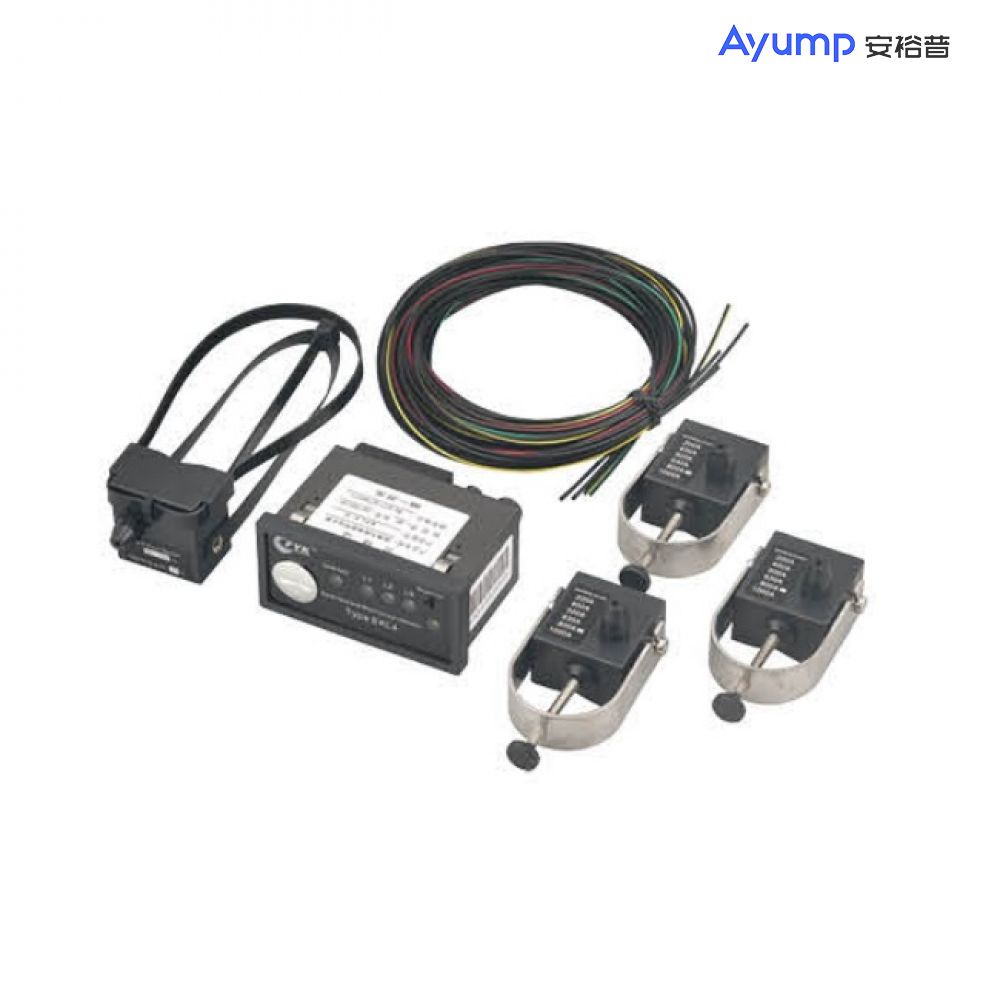
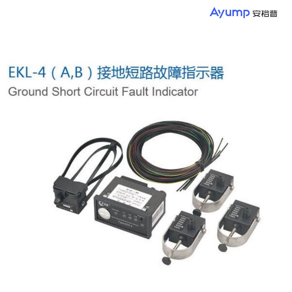
EKL-4 ( A,B ) Ground Short Circuit Fault Indicator
接地短路故障指示器")
Characteristics
The ground short-circuit fault indicator is divided into two types, A and B. The type B has a signal remote transmission function. It is a kind of automatic monitoring special device designed for urban and rural power gnid ring network distribution system based on digestion and absorption of similar advanced products at home and abroad. In a ring network power distribution system, especially in a system that uses a large number of ring load switches (Ring MainUnit), if a line short circuit or a ground fault occurs in the next-level power distribution network system, the upper-level power supply system must Break within a specified time to prevent major accidents. After the disconnection protection occurs, all systems belonging to this level of network will be powered off. By using this product, the faulty part can be quickly and accurately indicated, which greatly saves the time for finding the fault part, reduces the power outage time and power outage range, and improves the relibility of power supply.
working principle
When there is a short circuit or a ground fault in the power supply line, the electromagnetic field generated by the short circuit or the ground curent changes, so that the measuring coil of the sensor fixed on the cable generates a pulse signal, and when the value of the pulse signal reaches or exceeds the set fault current value When the fault indicator automatically remembers the fault status, the fault indicator flashes to indicate the fault, and at the same time, the fault signal is transmitted to the monitoring center through the remote alarm interface, and the staff can quickly and accurately find the fault location of the line through the fault grenade signal. Troubleshoot and restore grid power.
Wiring diagram
接地短路故障指示器")
Ground Short Circuit Fault Indicator
Installation method and installation diagram
Installation steps are as follows:
1. The main unit of the indicator is installed on the front panel of the power distribution cabinet.
接地短路故障指示器 安装图1")
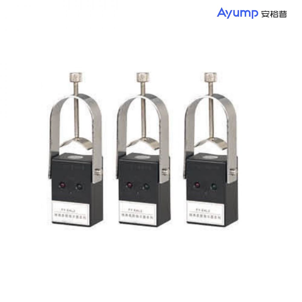
2. Install three short-circuit current sensors on the three phases A, B and C of the cable, and fasten them to the tested line.
接地短路故障指示器 安装图2")
3. Install the grounding current sensor at the lower end of the three-way cable of the three-phase cable, and the yoke should surround the three phases.
Guide tape type (short circuit sensor)
U-shaped hook (short-circuit sensor)
The main technical parameters
Project | parameter |
Ambient temperature | -35℃-+75℃ |
Environment humidity | ≤85% |
Pollution level | JP40 |
Protection level | JP65 |
Autormatic reset time | 4.8.12.24H |
Line voltage level | 35kV the following |
Power consumption | Standby operating current<5uA |
battery capacity | 3.6V lithium battery 2Ah:life span5年 |
Relay capacity | 230VAC 2A |
Short circuit alarm current | ≥300A continuously adjustable (factory setting) |
Grounding alarm current | ≥10A continuously adjustable (factory setting) |
Accuracy | Full temperature range error<±10% |
Trigger delay time | 20-300r-ns adjustable (factory setting) |
Withstand current capability | ≥20 kA 2S |
Applicable cable outer diameter | Single core ≤ 40mim |
Single set weight | <1000g |
Hole Size | 92×44mm |


 Scan to add WeChat